
Views: 0 Author: Site Editor Publish Time: 2026-09-01 Origin: Site


Premature mechanical seal failure and bearing wear in fluid systems are frequently misdiagnosed as manufacturer defects. The root cause is often improper piping support inducing severe stress on the pump casing. Inline pumps are marketed for easy pipeline integration without requiring massive concrete foundations. This creates a dangerous assumption on the job site. Many installers assume these units require zero structural planning. Engineers and contractors face conflicting industry advice regarding installation. They debate whether the piping should support the pump or if the pump requires independent structural anchoring. Incorrect implementation leads to equipment failure, voided warranties, and costly facility downtime. This guide provides a definitive, engineering-backed framework for supporting an inline Surface Pump. We detail load distribution rules, flange alignment tolerances, and mitigation strategies for thermal and dynamic pipe stress.
Defining operational expectations of inline pumps versus traditional base-mounted units is essential for long-term reliability. Facilities choose inline designs primarily for spatial efficiency and simplified piping layouts. Understanding their specific load paths remains necessary to prevent mechanical failure. When you ignore the structural dynamics of the volute and motor mass, you invite rapid component degradation.
Load paths differ significantly between an inline centrifugal water pump and a traditional frame-mounted unit. Inline units transfer structural loads directly through the pipeline axis. The casing acts as a continuation of the pipe itself. Frame-mounted pumps transfer load downward into a rigid concrete inertia base. The center of gravity shifts drastically depending on the installation orientation.
Vertical inline installations place the entire motor mass directly above the volute. This configuration creates a high center of gravity. Any lateral movement in the piping system creates a massive lever effect, amplifying stress at the flange connections. Horizontal installations cantilever this motor weight outward. This cantilever effect introduces a twisting moment on the pipeline. These geometric differences dictate entirely different support strategies to prevent shaft deflection and maintain internal clearances.
Look at a typical 50 HP vertical inline unit. The motor alone can weigh over 600 pounds. If the adjacent piping shifts even a quarter inch due to thermal expansion, that 600-pound mass acts as a fulcrum. The mechanical seal faces, which rely on microscopic fluid films, get crushed on one side and pulled apart on the other. You will see a steady drip from the seal gland within a week of startup. Frame-mounted units avoid this by bolting the volute and motor to a shared steel skid, which is then grouted to the floor. Inline units lack this shared skid. The pipe hangers must do the heavy lifting.
Different pump designs demand unique structural considerations based on their internal mechanics and casing geometries. The inline centrifugal design integrates directly into straight pipe runs, making it unique among fluid handling equipment. Other configurations require much more rigid foundation planning.
A self priming centrifugal pump requires rigid baseplate mounting. Offset suction and discharge geometries create uneven weight distribution across the casing. Dynamic priming forces generate significant vibration during startup phases. You cannot rely on adjacent piping to stabilize these forces. The internal liquid reservoir needed for the priming cycle adds eccentric weight that shifts during operation.
Similarly, a jet water pump needs a solid foundation to handle internal ejector dynamics and prevent harmonic resonance from traveling through the system. Jet pumps utilize a venturi mechanism that creates high-velocity pressure zones. If the casing isn't bolted down, this internal turbulence translates into physical shaking that will back off flange bolts over time.
Rigid mounting is equally necessary for a peripheral water pump. These units operate with extremely tight internal clearances between the impeller and the casing. Any casing deflection from pipe strain immediately degrades hydraulic performance. The resulting distortion causes the brass or bronze impeller to rub against the volute walls. This metal-on-metal contact destroys the pump within hours of operation.
Industry contradictions regarding inline pump support confuse many installers and system designers. We must establish clear engineering thresholds to determine proper load distribution. Relying on outdated rules of thumb leads to inconsistent installation quality across different facility zones.
Piping can support the pump under very specific, tightly controlled conditions. Fractional horsepower circulators often fall into this category. Lightweight volutes and units featuring robust, integrated bearing assemblies tolerate pipe-mounting exceptionally well. Safe thresholds typically limit this approach to pipe diameters under three inches and motor weights below fifty pounds. Hydronic heating systems frequently utilize this method for small zone circulators.
Adding supplemental support to a pipe-supported bearing assembly pump requires extreme caution. You must engineer this addition carefully. Improperly placed supports create a rigid binding point in an otherwise flexible system. This rigid point fights the natural thermal movement of the piping network. The resulting stress fractures pipe joints, shears flange bolts, or permanently distorts the pump casing. If the pipe supports the pump, let the pipe move naturally.
Consider a standard 1/6 HP bronze circulator on a domestic hot water loop. The copper piping easily handles the 15-pound weight. If an overzealous contractor adds a rigid unistrut support directly under the circulator motor, they create a fixed anchor. When the hot water hits the copper line, the pipe expands. Since the pump is now locked in place, the expanding copper pushes against the pump flanges. The weakest point will yield, usually resulting in a cracked bronze volute or a blown flange gasket.
Larger inline pumps demand independent structural support without exception. The physics of casing stress dictate this strict requirement. The combined weight of a heavy NEMA-frame motor, internal fluid volume, and dynamic operational forces creates severe bending moments. Cast iron and even stainless steel volutes possess limited tensile strength. These moments distort the pump casing if left unsupported.
Independent support hardware directly prevents mechanical seal distortion. Clevis hangers, rigid stanchions, and saddle supports carry the structural load. This isolation prevents shaft deflection. Keeping the shaft perfectly straight ensures the rotating assembly remains centered within the stationary casing. When the shaft deflects even a few thousandths of an inch, mechanical seal faces separate, causing immediate fluid leakage and eventual bearing seizure.
Let's break down the math on a 10-inch inline pump moving chilled water. The pump and motor weigh 1,200 pounds. The water inside the volute adds another 150 pounds. If the adjacent 10-inch piping is unsupported for ten feet in either direction, you add hundreds of pounds of steel and water weight bearing down on the pump flanges. The pump casing becomes the lowest point of a massive suspension bridge. The cast iron will flex. The shaft will bend. The bearings will scream. You must install independent supports to carry this load.
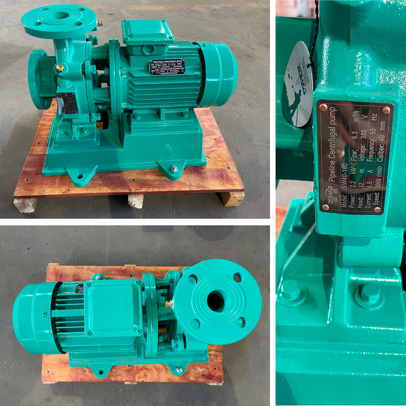
Technical requirements focus heavily on isolating the pump from external forces. Proper execution ensures optimal hydraulic performance and extends equipment lifespan significantly. Field execution must match the engineering drawings exactly to achieve these results.
Install rigid pipe supports or hangers as close to the pump suction and discharge flanges as practically possible. This proximity isolates the pump from the broader pipeline weight. The first support should bear the entire static weight of the vertical pipe drop. Place subsequent supports according to standard pipe span tables based on diameter and material.
Use adjustable supports during the installation phase. Adjustable hardware, such as threaded rod clevis hangers, allows you to fine-tune elevation during bolt-up. The pipe must meet the pump perfectly. The pump should never be pulled up or pushed down to meet the pipe. Adjustable supports give pipefitters the exact control needed to achieve zero-strain alignment.
A common field mistake involves welding fixed stanchions before the pump is actually bolted in place. The welder sets the stanchion based on the drawing elevation. When the pump arrives, the flange is an eighth of an inch off. The crew then uses a pry bar to force the pipe down to meet the pump. This is a guaranteed failure. Always use adjustable saddle supports or threaded rods for the first support point. Bring the pipe to the pump, adjust the support to hold it exactly there, and then tighten the flange bolts.
Hydraulic stability requires a minimum of 5 to 10 pipe diameters of straight, independently supported pipe on the suction side. Horizontal Split Case (HSC) pumps can often tolerate inlet bends. Their internal geometry provides a straightening effect from the inlet flange to the impeller eye. Inline centrifugal pumps lack this internal advantage. They demand strict straight runs to prevent turbulent flow from entering the impeller.
Improper support of upstream fittings induces both mechanical strain and hydraulic turbulence. Heavy isolation valves, elbows, and foot valves must have dedicated anchors. Sagging upstream components create high points where air pockets accumulate. These air pockets eventually break loose, entering the pump and triggering severe cavitation inside the volute. Cavitation pits the impeller metal and destroys bearings through intense vibration.
The 5 to 10 pipe diameter rule is a minimum baseline. For a 4-inch pump suction, you need 20 to 40 inches of straight pipe. If you are pumping viscous fluids or operating near the fluid's vapor pressure, you need even more straight run to ensure uniform velocity distribution at the impeller eye. When installing a reducer to transition from a larger header down to the pump suction, always use an eccentric reducer, not a concentric one. Install the eccentric reducer with the flat side up. This prevents air bubbles from trapping at the top of the pipe. A concentric reducer creates a high point where air accumulates. When that air pocket breaks loose and hits the impeller, it causes an air-lock, instantly dropping the pump's flow rate to zero and causing the mechanical seal to run dry and burn up.
| Pump Type / Configuration | Primary Support Method | Vibration Isolation Requirement | Critical Alignment Focus |
|---|---|---|---|
| Fractional HP Inline Circulator | Pipe-supported (Suspended) | Minimal (Rely on pipe flexibility) | Flange face parallel alignment |
| Industrial Vertical Inline | Adjacent rigid pipe hangers | Spring hangers (if building structure requires) | Zero axial strain on casing |
| Horizontal End Suction | Concrete inertia base / Baseplate | Inertia pad with spring mounts | Motor-to-pump shaft coupling |
| Large Capacity Split Case | Grouted steel baseplate | Flexible pipe connectors | Baseplate leveling before grouting |
Piping flanges must mate with the pump flanges perfectly flush and concentric. This alignment must occur without using chain falls, pry bars, or excessive bolt torque. If a pipefitter uses a come-along to pull a pipe into position, that tension transfers directly into the pump casing the moment the bolts tighten.
Verify zero-strain installation before final torqueing using the free-bolting test. Bring the pipe flange flush against the pump flange. Insert the flange bolts by hand. If you cannot push the bolts through the mating holes freely, the pipe is misaligned. You must adjust the pipe hangers until the bolts slide in without resistance. Forcing the bolts introduces immediate, destructive strain into the pump casing.
The tolerance for flange alignment is incredibly tight. The gap between the pipe flange and the pump flange should be uniform around the entire circumference, typically within 1/32 of an inch. The bolt holes must align perfectly. You should not need to use a drift pin to line up the holes. If the pipe is twisted, you must cut and re-weld the flange or adjust the upstream hangers to remove the torsion. Bolting up a twisted pipe puts a torsional load on the pump casing. Over time, this twisting force will warp the volute, causing the internal wear rings to rub against the impeller. You will hear a high-pitched squeal from the pump, followed by a rapid drop in motor efficiency as the friction increases the electrical amp draw.
Dynamic variables alter support effectiveness after commissioning. Regular operation introduces thermal and hydraulic forces requiring proactive management. A system perfectly aligned when cold and empty behaves very differently when filled with hot, pressurized fluid.
Temperature fluctuations in the pumped fluid cause piping to grow or shrink. Steel pipe expands roughly 0.75 inches per 100 feet per 100 degrees Fahrenheit of temperature rise. Rigidly constrained pipes transfer massive axial loads directly into the pump casing. This thermal expansion easily exceeds the structural limits of cast iron volutes, causing them to crack or shatter.
Mitigate these forces through proper system design and careful hanger placement. Integrate expansion joints, engineered pipe loops, and sliding supports. These components direct thermal movement away from the pump flanges. Anchor the pipe securely just past the expansion joint. This setup forces the joint to absorb the dimensional changes, protecting the pump from axial thrust.
When designing for high-temperature fluids like boiler feed water or thermal oils, the expansion rates increase dramatically. A carbon steel pipe carrying 350-degree thermal oil will expand over two inches per hundred feet. You cannot simply bolt this to a cast iron pump flange. The system requires engineered expansion loops. These loops use four 90-degree elbows to create a U-shape in the piping run. As the straight pipe expands, the elbows flex, absorbing the growth. You must place directional anchors on either side of the loop to force the expansion into the U-shape and away from the pump. If space constraints prevent expansion loops, you must install inline bellows expansion joints. These corrugated metal joints compress as the pipe grows. However, bellows joints exert pressure thrust. The internal fluid pressure tries to stretch the bellows apart. You must install heavy-duty control rods across the bellows to limit this extension, or the thrust force will push right through the joint and shatter the pump volute.
Engineers must evaluate trade-offs between rigid hangers and spring-loaded vibration isolators. Rigid hangers provide excellent static support and maintain precise alignment. However, they transmit operational vibration directly into the building structure. Spring hangers absorb vibration effectively, protecting the building acoustics.
Improperly tuned spring hangers introduce severe mechanical risks. Operational pressure changes or fluid density shifts alter the pipeline weight. If the springs are not calibrated correctly, they compress or extend unexpectedly during startup. This uncontrolled movement inadvertently transfers piping weight back onto the pump casing. Always use spring hangers equipped with travel limit stops to prevent excessive vertical movement during system pressure transients.
Selecting the right vibration isolator requires understanding the system's operating frequency. A pump running at 1750 RPM generates a specific vibration signature. If the natural frequency of the pipe hanger matches this operating frequency, you get harmonic resonance. The vibration amplifies, shaking the pipe violently. To prevent this, engineers specify spring hangers with a static deflection that ensures the hanger's natural frequency is significantly lower than the pump's operating frequency. Neoprene pads work well for high-frequency noise, but steel springs are necessary for low-frequency mechanical vibration. When installing these springs, the contractor must adjust the load nut until the spring compresses to the engineered deflection point. Only then do you remove the factory travel stops. If you remove the stops before adjusting the load, the pipe will drop, and the pump casing will take the full weight of the water-filled pipe.
Perform dial indicator testing on the pump shaft while loosening flange bolts. Mount the magnetic base of the dial indicator to a rigid surface and place the needle on the pump shaft or coupling hub. Slowly loosen the flange bolts. If the dial indicator shows movement exceeding manufacturer tolerances (typically 0.002 inches), the pipe is pulling on the pump. You must realign the piping supports.
Verify hanger load distribution post-hydrostatic testing. Pipes full of water weigh significantly more than empty pipes. This fluid weight alters the dynamic load on every hanger in the system. Inspect all spring hangers to ensure they have not bottomed out. Ensure all rigid hangers carry their designated share of the operational weight before starting the motor for the first time.
Follow this exact sequence to verify zero strain before startup:
Inline pumps offer easy pipeline integration but are not structural components. Treating them as load-bearing pipe anchors guarantees premature mechanical seal failure and bearing destruction. Engineers and installers must select support hardware based on fluid temperature, pipe diameter, and specific bearing configurations to ensure long-term reliability.
A: Yes, most inline pumps accommodate both orientations. Vertical installations place the motor above the volute, requiring adjacent pipe hangers to carry the load. Horizontal installations cantilever the motor weight outward, often requiring a dedicated stanchion or sling support under the motor to prevent twisting the pipeline.
A: The sequence of failure begins with casing deflection. This distortion causes shaft misalignment. The misaligned shaft separates the mechanical seal faces, causing fluid leakage. Eventually, the uneven load destroys the bearings, leading to complete pump seizure and potential motor burnout.
A: Traditional base-mounted pumps require concrete inertia bases. Standard inline pumps rely entirely on adjacent pipe supports and do not need a concrete pad. However, very large vertical inline pumps may require a baseplate or pedestal directly under the volute to handle extreme weights.
A: Place the first set of rigid pipe supports immediately adjacent to the suction and discharge flanges. This standard practice isolates the pump from the wider piping system's weight, ensuring the pump casing experiences zero static or dynamic load from the pipeline.
A: Flexible connectors isolate vibration and absorb thermal expansion effectively. However, they must be properly anchored with control rods. Without control rods, internal fluid pressure thrusts the piping outward, stretching the connector and pushing massive force directly into the pump casing.


