
Views: 0 Author: Site Editor Publish Time: 2026-09-25 Origin: Site


Micro-tolerances within a pump casing dictate the macro-performance of fluid transfer systems, particularly in high-pressure applications. When unexplained system pressure drops, increased energy consumption, and premature mechanical failures occur, the root cause often traces back to internal fluid recirculation and volumetric slip. Addressing these operational inefficiencies requires a deep understanding of internal mechanics rather than superficial system tweaks. Evaluating impeller-to-casing clearance serves as a critical diagnostic metric for identifying performance loss.
By mastering this technical parameter, operators can specify the correct pump architecture, establish rigorous preventative maintenance protocols, and ensure optimal fluid delivery across demanding environments. Fluid dynamics within a regenerative casing rely entirely on maintaining specific physical boundaries. When those boundaries degrade, the entire system suffers. Understanding how to measure, adjust, and maintain these clearances separates a highly optimized fluid transfer system from one plagued by chronic failure and energy waste.
High-head, low-flow applications present a unique fluid dynamics challenge. Standard pump designs often fail to meet these pressure demands without relying on complex, multi-stage configurations. A single-stage standard pump simply cannot impart enough kinetic energy to the fluid to overcome significant vertical lifts or high-resistance filtration systems. Operators need a solution that generates massive discharge pressure without requiring a massive physical footprint. The success criteria for these applications hinge on maximizing energy transfer within a compact casing. This requirement birthed the regenerative turbine design, where fluid behavior is manipulated through extreme physical constraints to build pressure incrementally within a single rotation. In field applications like boiler feed systems or reverse osmosis units, hitting exact pressure targets is non-negotiable, making the internal geometry of the pump the deciding factor in system success.
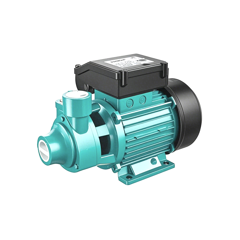
Peripheral pumps operate on a regenerative principle. The impeller features dozens of small vanes machined into its periphery. As fluid enters the casing, it is caught by these vanes and accelerated. Unlike standard designs where fluid passes through the impeller once, fluid in a peripheral pump spirals in and out of the impeller vanes repeatedly as it travels from the suction port to the discharge port. This continuous regenerative action imparts high-velocity kinetic energy to the fluid. However, kinetic energy alone does not equal system pressure. The tight casing clearance is strictly required to convert that speed energy into usable system pressure. The casing acts as a physical barrier, forcing the rapidly moving fluid to compress and build head pressure before exiting the discharge nozzle. Without this tight physical boundary, the fluid would simply scatter, losing all accumulated kinetic energy.
The fundamental difference in operation dictates a massive difference in manufacturing tolerances. A peripheral water pump requires radial and axial clearances measured in thousandths of an inch. These micro-tolerances are necessary to maintain the continuous regenerative pressure cycle. If the gap between the impeller and the casing is too wide, the fluid simply slips past the vanes rather than being forced back into the regenerative spiral. Contrast this with the relatively wider volute clearances found in a standard centrifugal water pump. Standard centrifugal designs rely on centrifugal force throwing the fluid outward into a widening volute to build pressure. They do not rely on continuous fluid recirculation, meaning they can tolerate significantly larger gaps between the impeller and the casing without suffering an immediate, catastrophic loss of head pressure.
| Pump Architecture | Typical Clearance Range | Primary Pressure Mechanism | Sensitivity to Abrasive Wear |
|---|---|---|---|
| Peripheral Pump | 0.1mm - 0.3mm | Regenerative fluid recirculation | Extremely High |
| Standard Centrifugal | 0.5mm - 1.5mm | Centrifugal force into volute | Moderate |
| Jet Pump | 0.5mm - 1.0mm | Venturi ejector nozzle | Low to Moderate |
Volumetric slip is the silent destroyer of pump efficiency. It occurs when fluid leaks from the high-pressure discharge zone back to the low-pressure suction zone through excessive clearance gaps. In a peripheral pump, the pressure differential between the discharge and suction sides is immense. Fluid will always seek the path of least resistance. If the impeller clearance widens due to wear, the fluid bypasses the discharge port and recirculates internally. This effectively short-circuits the pump. The motor continues to draw power and spin the impeller, but the fluid is merely churning inside the casing rather than moving through the piping system. This internal recirculation drastically reduces the net flow rate and destroys the discharge pressure. Field technicians often measure this by dead-heading the pump briefly; if the maximum pressure falls significantly below the manufacturer's curve, volumetric slip is the primary suspect.
Setting the correct clearance is a delicate balancing act. Incorrect spacing carries severe operational penalties. If the clearance is set too tight, the system suffers from increased mechanical friction. The fluid film between the impeller and casing becomes too thin to provide adequate lubrication, leading to rapid heat generation. This thermal buildup transfers to the fluid and the mechanical components, increasing the motor load and risking a seized rotor. Conversely, too loose a clearance destroys volumetric efficiency. The pump expends energy accelerating fluid that simply slips back to the suction side. This hydraulic inefficiency means the pump must run longer and harder to move the same volume of fluid, wasting electricity and accelerating the wear of bearings and mechanical seals. Operators must find the exact middle ground where fluid slip is minimized but mechanical contact is entirely avoided.
In pumps utilizing closed impellers, the wear ring insertion depth plays a critical role in controlling internal leakage. The annulus is the narrow gap between the rotating impeller wear ring and the stationary casing wear ring. Lowering the impeller or adjusting the rotor assembly increases this insertion depth. A deeper insertion improves the pressure drop across the annulus. By forcing the fluid to travel a longer, more tortuous path through the tight clearance gap, the velocity of the leaking fluid decreases. This stabilizes internal flow dynamics and ensures that the maximum amount of fluid is directed out of the discharge port rather than slipping back to the suction eye. Managing this annular gap requires precision machining and regular inspection during scheduled maintenance windows.
The most immediate diagnostic indicator of clearance degradation is a failure to hit the specified point on the pump curve. Operators will notice decreased flow rates and a distinct system pressure loss. When commissioning a pump, it operates at a specific intersection of head and flow. As internal clearances widen, hydraulic losses increase. The pump curve effectively shifts downward. A pump that previously delivered 50 PSI at 100 gallons per minute may drop to 35 PSI at the same flow rate. This performance gap is rarely caused by motor degradation; it is almost always the result of volumetric slip caused by worn internal clearances. Relying on flow meters and pressure gauges installed directly at the discharge nozzle provides the most accurate data for diagnosing this specific mechanical failure.
System automation often masks the early symptoms of clearance wear. Variable frequency drives or pressure switches will automatically compensate for pressure loss by running the pumps longer or at higher speeds. While this maintains system output temporarily, it leads to hidden electrical costs and accelerated mechanical wear. Operators evaluating power consumption logs will see a steady increase in amperage draw for the same volume of fluid transferred. The motor is straining to overcome the hydraulic inefficiency of the worn pump casing. This increased duty cycle degrades motor insulation, shortens bearing life, and ultimately leads to premature electrical failure. Monitoring baseline amperage during initial commissioning provides a reference point to track this gradual degradation over time.
Excessive back clearance fundamentally alters internal pressure dynamics. The area behind the impeller, near the mechanical seal, relies on specific pressure gradients to remain stable. A lack of discharge-side wear rings or widened back clearances can cause dangerous pressure increases at the seal chamber. High-pressure fluid bypasses the impeller and floods the stuffing box, risking mechanical seal blowout and catastrophic fluid leaks. Furthermore, altered internal flow dynamics can induce localized pressure drops near the suction eye. If the pressure drops below the fluid's vapor pressure, cavitation occurs. This risk is present even in a self priming centrifugal pump or a jet water pump, where disrupted flow patterns can create low-pressure eddies that boil the fluid and destroy the impeller metal. The resulting vibration from cavitation further accelerates bearing and seal wear, creating a compounding cycle of mechanical failure.
Pump manufacturers utilize different impeller designs to handle varying fluid types and operational requirements. These designs are broadly categorized into open, semi-open, and closed impellers. Each category features distinct clearance adjustment mechanisms and unique vulnerabilities to wear. Selecting the right impeller type dictates how the maintenance team will handle clearance degradation over the lifespan of the equipment. Understanding these solution approaches is vital for aligning the pump architecture with the realities of the installation environment. A mismatch here guarantees excessive downtime and inflated maintenance budgets.
Closed impellers feature shrouds on both sides of the vanes, creating enclosed fluid channels. Because the fluid is contained within the impeller, radial clearance against the main casing wall is less critical. Instead, closed impellers rely entirely on casing wear rings and impeller wear rings to maintain the necessary pressure differential between the discharge and suction zones. These rings form a tight annular gap. Over time, particulate matter in the fluid grinds away at these rings. They are designed as sacrificial components. The maintenance reality of a closed impeller system involves monitoring the wear ring gap and scheduling tear-downs to press out old rings and install new ones before volumetric slip severely impacts performance. Ignoring this maintenance task leads to the impeller rubbing directly against the casing, requiring a complete pump replacement.
Closed impellers offer high efficiency but present a significant high-clog risk when handling fluids with suspended solids. Debris easily becomes trapped within the enclosed shrouds, requiring a complete pump disassembly to clear. Contrast this with the operational advantage of open impellers. Open impellers lack shrouds, exposing the vanes directly to the fluid and the casing wall. They are significantly less likely to clog and much easier to clean. When handling fluids with stringy materials or heavy particulates, open impellers maintain operational continuity far better than their closed counterparts, albeit at a slight cost to peak hydraulic efficiency. Facility managers often accept this minor efficiency drop in exchange for the massive reduction in unplanned downtime caused by clogged fluid channels.
Maintaining performance in semi-open and open designs requires different maintenance techniques. Because there are no wear rings, volumetric slip is controlled by the axial clearance between the edge of the impeller vanes and the stationary casing or wear plate. Performance is restored by physically adjusting the rotor assembly. Mechanics perform an impeller lift, utilizing shims or threaded shaft adjustments to close the gap against the casing. Additionally, open impeller blades can be cut or trimmed on a lathe to modify clearance dynamics and flow rates. This trimming process reduces the impeller diameter, altering the pump curve according to the affinity laws and offering a customizable approach to optimizing the pump for specific system requirements. Trimming must be executed with extreme precision to avoid unbalancing the rotor and inducing destructive vibration.
Field adjustments of impeller clearances carry significant practical challenges. Mechanics must work with precision instruments in less-than-ideal environments. The primary risk is setting the clearance too tight while the pump is offline and cold. When the pump begins operating, the fluid and the mechanical friction generate heat. The metal components expand. If thermal expansion is not accounted for during the cold-setting process, the expanding impeller will grind against the casing, leading to catastrophic seizing, shattered mechanical seals, and bent shafts. Mitigating this risk requires strict adherence to manufacturer expansion charts and utilizing conservative baseline settings during initial commissioning. You cannot guess these measurements; relying on tactile feel rather than calibrated instruments is a guaranteed path to equipment failure.
Engineering consensus dictates strict baseline tolerances for peripheral designs. Depending on the physical size of the pump and the metallurgy of the casing, standard clearance ranges typically fall between 0.1mm to 0.3mm. Achieving this level of precision is impossible by eye. Mechanics must utilize precision measurement tools during assembly. Feeler gauges are used to measure the static gap between the vanes and the casing wall. Dial indicators are mounted to the shaft to measure radial runout and ensure the impeller is spinning perfectly true within the casing. Any deviation beyond the specified tolerance guarantees immediate performance degradation. If the shaft exhibits excessive runout before the clearance is even set, the bearings or the shaft itself must be replaced first.
Maintenance managers must weigh the labor hours, downtime, and technical complexity of different clearance restoration methods. Replacing wear rings on a closed impeller is a heavy maintenance task. It requires isolating the pump, removing the casing, pulling the rotor assembly, and often using a hydraulic press or thermal heating to remove and install the new rings. This results in significant system downtime. Conversely, performing axial adjustments on an open impeller is often much faster. Mechanics can adjust the external thrust bearing housing or utilize external shims to push the entire shaft and impeller assembly closer to the wear plate, restoring performance in a fraction of the time required for a full tear-down. This speed of repair makes open impeller designs highly attractive for continuous-process facilities.
Operating temperatures and fluid properties must dictate the cold-setting of impeller clearances. A pump handling ambient water will experience minimal thermal growth. However, a pump transferring hot boiler feed water will experience significant expansion. The cold clearance must be set wide enough to accommodate this growth without risking galling during operation. Furthermore, fluid viscosity impacts clearance decisions. Highly viscous fluids create thicker lubricating films and generate more internal friction heat. Mechanics must adjust baseline tolerances to account for the specific thermodynamic behavior of the pumped fluid, ensuring the rotor spins freely at full operating temperature.
Specifying a pump based solely on initial purchase price guarantees long-term operational failure. Procurement must focus on long-term tolerance stability. The evaluation framework should connect physical pump features to operational outcomes. A pump with heavy-duty thrust bearings will resist axial shaft movement, maintaining tight clearances longer than a cheaper model with standard bearings. Similarly, a casing designed with easily accessible external adjustment mechanisms reduces maintenance downtime, directly impacting the facility's operational efficiency. Procurement engineers must evaluate how easily a pump can be brought back to factory tolerances after a year of continuous operation. If restoring clearance requires shipping the unit back to a machine shop, the operational cost will rapidly outpace the initial savings.
Metallurgy is the primary defense against clearance degradation. The impact of material selection on maintaining clearance integrity cannot be overstated, especially against abrasive or corrosive fluids. Standard cast iron provides adequate performance for clean water but degrades rapidly when exposed to sand or grit. Bronze offers excellent galling resistance, making it ideal for tight-clearance wear rings, but it lacks the hardness to survive heavy abrasives. For demanding environments, hardened stainless steel or specialized duplex alloys are required. These materials resist both chemical corrosion and physical abrasion, ensuring the micro-tolerances remain intact for thousands of operating hours. Upgrading the impeller and casing material during the procurement phase is the most effective way to extend the mean time between failures.
Engineering is the science of trade-offs. Facility managers must weigh the high-pressure capabilities of a peripheral pump against its extreme sensitivity to suspended solids. If the fluid contains particulate matter, the micro-clearances of a peripheral design will rapidly erode, destroying performance. In less pristine fluid environments, operators must pivot their strategy. Determine when a multi-stage centrifugal design or a robust jet pump offers a more resilient operational profile. While these alternatives may require a larger physical footprint or consume slightly more power initially, their ability to maintain performance despite minor internal wear makes them a superior choice for abrasive applications. Selecting the right Surface Pump requires matching the internal architecture perfectly to the fluid reality of the site.
A: Standard clearances for peripheral pumps are extremely tight, typically ranging from 0.1mm to 0.3mm depending on the pump size and casing metallurgy. These micro-tolerances are required to maintain the regenerative pressure cycle and prevent fluid from slipping backward during operation.
A: Excessive clearance allows high-pressure fluid at the discharge port to leak back into the low-pressure suction zone. This internal recirculation, known as volumetric slip, short-circuits the pump. The motor expends energy churning the fluid internally rather than pushing it through the piping system.
A: Yes, if the pump utilizes an open or semi-open impeller. Mechanics can perform an axial adjustment, often called an impeller lift, by adding shims or adjusting the thrust bearing housing to move the impeller closer to the wear plate, thereby restoring lost performance.
A: Setting the clearance too tight eliminates the lubricating fluid film between the impeller and casing. This causes severe mechanical friction, rapid heat generation, motor overload, and ultimately leads to the rotor seizing and catastrophic mechanical failure.
A: Inspection intervals depend heavily on fluid quality. For clean water applications, wear rings should be inspected during annual maintenance tear-downs. If pumping abrasive fluids, inspections should occur semi-annually or whenever a 10% drop in discharge pressure is recorded.
A: Yes. While clearance matters in both, a jet pump relies on an ejector nozzle and venturi tube to build pressure, making it slightly more tolerant of minor impeller wear. A peripheral pump relies entirely on micro-clearances for its regenerative action, making it highly sensitive to any degradation.


