
Views: 0 Author: Site Editor Publish Time: 2026-09-28 Origin: Site


Overcoming gravity in commercial facilities requires precise hydraulic engineering. Miscalculating vertical elevation causes catastrophic plumbing failures and chronic low-pressure complaints. Specifying engineers and facility managers must balance the physical reality of static head against municipal supply fluctuations and complex friction penalties. Undersizing results in inadequate flow on upper floors and code violations. Oversizing leads to excessive energy consumption, pipe degradation, and blown fixtures.
To specify the correct equipment, decision-makers must move beyond basic floor counts. You must evaluate Total Dynamic Head (TDH), flow rate estimations, zoning architectures, and modern variable speed technologies to ensure reliable water delivery. Understanding the exact relationship between vertical lift and pump performance prevents costly retrofits. It ensures that every fixture operates at optimal pressure, regardless of its location in the building.
Static head represents the absolute vertical distance water must travel from the pump discharge to the highest fixture. Gravity exerts a constant downward force on the water column. Overcoming this force requires specific mechanical energy. The mathematical relationship is absolute. One pound per square inch (PSI) of pressure lifts a column of water exactly 2.31 feet. Conversely, every foot of vertical elevation requires 0.433 PSI to push water upward.
Commercial structures typically feature floor-to-floor heights of 10 to 12 feet. A twenty-story hotel with 12-foot ceilings presents 240 feet of vertical lift. Dividing 240 by 2.31 reveals a baseline requirement of 103.8 PSI simply to reach the top floor. This calculation only overcomes gravity. It does not account for the pressure required to operate the fixtures once the water arrives. Flushometer valves on commercial toilets often require a minimum of 35 to 45 PSI to function correctly. Adding this residual requirement to the elevation lift establishes the absolute minimum static head.
Water does not flow upward without resistance. As water travels through vertical risers and horizontal branches, it drags against the interior pipe walls. This friction loss consumes pump energy. Pipe material, internal diameter, and the number of directional changes dictate the severity of this loss. Copper piping offers different friction coefficients than PEX or CPVC. As pipes age, mineral scale builds up internally. This increases surface roughness and compounds friction penalties over the lifespan of the plumbing system.
Hidden penalties exist within the mechanical room itself. Commercial water meters restrict flow and induce pressure drops. Complex valve assemblies, strainers, and elbows further degrade system pressure before water even leaves the basement. Backflow prevention devices, specifically Reduced Pressure Zone (RPZ) assemblies, are notorious for consuming pressure. An RPZ valve can easily strip 10 to 15 PSI from the system depending on the flow rate. You must calculate these specific pressure drops and add them to the static head requirement.
| System Component | Typical Pressure Drop (PSI) | Impact on TDH Calculation |
|---|---|---|
| Reduced Pressure Zone (RPZ) Valve | 10 - 15 PSI | High impact; must be added to total head requirements. |
| Commercial Water Meter (Turbine) | 3 - 8 PSI | Moderate impact; varies heavily based on peak GPM flow. |
| Standard Check Valve | 1 - 3 PSI | Low impact; cumulative effect matters in complex manifolds. |
| Y-Strainer (Clean) | 1 - 2 PSI | Low impact initially; increases significantly as debris builds up. |
Incoming city water pressure acts as a baseline credit against your total required head. If your building requires 120 PSI at the base to satisfy the top floor, and the city provides a reliable 50 PSI, the pump only needs to generate the remaining 70 PSI. This direct tie-in scenario allows engineers to specify smaller, more efficient equipment.
Water sources dictate system design. Drawing from an atmospheric break tank at the building's base changes the math entirely. A break tank severs the connection to municipal pressure. The water rests at atmospheric pressure, meaning zero gauge pressure. In this scenario, the pump receives no municipal credit and must generate the entire 120 PSI independently. You must also account for seasonal municipal pressure drops. City infrastructure experiences heavy drawdowns during morning peak hours. Failing to calculate head based on the lowest recorded municipal pressure guarantees low-flow complaints on upper floors.
Calculating vertical lift provides an incomplete picture without an accurate estimation of volumetric flow. A pump capable of hitting 150 PSI is useless if it can only deliver 20 gallons per minute (GPM) when the building demands 300 GPM. Head and flow are intrinsically linked on every pump performance curve.
Engineers utilize Hunter's Curve and Water Supply Fixture Unit (WSFU) counts to determine peak GPM demand. Every toilet, sink, and shower carries a specific WSFU value. Summing these values and applying probability curves reveals the maximum simultaneous flow rate. You must ensure the selected water pressure booster pump can deliver this exact flow at the calculated maximum head. Mismatching these two variables leads to dead-heading, severe cavitation, or premature motor burnout.
A single-zone architecture utilizes one high-pressure pump set located at the building base. This single system pushes water to the very top of the structure. While cost-effective upfront, this approach creates severe pressure imbalances in tall buildings. To satisfy the top floor of a 15-story building, the base pressure must be extraordinarily high. Plumbing codes generally restrict fixture pressure to a maximum of 80 PSI to prevent damage to seals and flexible supply lines.
To mitigate this, pressure-reducing valves (PRVs) are installed on the lower floors. The PRVs throttle the excessive pressure down to safe levels. This introduces significant mechanical trade-offs. The pump consumes massive amounts of energy generating high pressure, only for the PRVs to burn that energy off as friction. PRVs require strict maintenance schedules. When a PRV fails, it typically fails in the open position. This exposes lower-floor fixtures to pipe-rupturing pressures, leading to catastrophic flooding and extensive property damage.
High-rise structures demand a different approach. Splitting the building into vertical pressure zones eliminates the extreme pressure gradients found in single-zone designs. A common configuration divides the building into blocks. For example, Zone 1 serves Floors 1-10, and Zone 2 serves Floors 11-20. Each zone is served by dedicated Booster Pump Sets.
This multi-zone architecture eliminates the need for PRVs on branch lines. It drastically reduces the maximum pressure rating required for piping, fittings, and valves in the lower sections of each zone. While this approach requires more mechanical space and higher initial capital expenditure, it yields significant long-term energy savings. Pumps operate closer to their optimal efficiency points. The risk of catastrophic high-pressure blowouts is virtually eliminated because no single pipe is subjected to the full hydrostatic head of the entire building.
Legacy high-rises often relied on gravity-fed roof tanks. Pumps at the base slowly filled massive wooden or steel tanks on the roof. Gravity then pressurized the downward feed lines. This method provided reliable pressure but introduced severe structural load implications. Water weighs 8.34 pounds per gallon. A 15,000-gallon tank adds over 125,000 pounds to the roof structure, requiring massive steel reinforcements.
Modern plumbing codes and health standards favor direct pumping. Roof tanks pose severe water quality and stagnation risks. Sunlight and warm temperatures create ideal breeding grounds for Legionella bacteria and algae. A modern constant pressure water supply system eliminates the need for stored water on the roof. Variable speed pumps react instantly to demand, maintaining exact pressure setpoints without the structural or biological liabilities of gravity tanks.
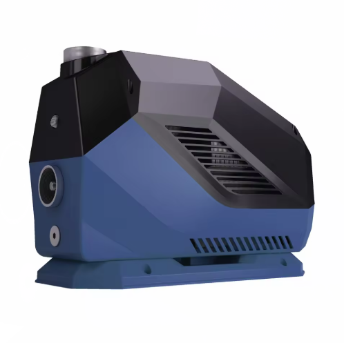
Pump geometry plays a critical role in mechanical room design. Vertical multistage pumps stack impellers vertically along a single shaft. This configuration offers a highly compact footprint. Vertical pumps excel at generating high head pressures, making them ideal for tight mechanical rooms in tall, narrow buildings. The vertical alignment naturally balances radial loads, contributing to longer bearing life under high-pressure conditions.
Conversely, a horizontal multistage booster pump lays the shaft parallel to the floor. While they consume more floor space, they provide superior maintenance access. Technicians can service the motor and mechanical seal without dismantling the entire piping manifold or using overhead lifting gear. Horizontal configurations are often preferred for high-flow, moderate-head applications, such as sprawling mid-rise complexes, hospitals, or large commercial campuses.
| Pump Configuration | Primary Advantage | Ideal Building Type | Maintenance Profile |
|---|---|---|---|
| Vertical Multistage | Minimal floor space, high vertical lift capabilities | High-rise towers, tight basement mechanical rooms | Requires vertical clearance for motor removal; harder to access lower seals. |
| Horizontal Multistage | High flow capacity, easy component access | Mid-rise campuses, sprawling commercial facilities | Excellent access to seals and bearings; no overhead lifting required. |
Commercial water demand is never static. A hotel experiences massive flow spikes at 7:00 AM as guests shower, and virtually zero demand at 2:00 AM. Traditional fixed-speed pumps run at 100% capacity regardless of demand, relying on mechanical valves to throttle excess pressure. This wastes immense amounts of electricity and accelerates wear on internal impellers and bearings.
Integrating a commercial inverter booster pump solves this inefficiency. Variable Frequency Drives (VFDs) alter the electrical frequency supplied to the motor. A pressure transducer mounted on the discharge manifold constantly reads system pressure and sends a signal back to the VFD's PID controller. As demand drops, the VFD slows the motor down. According to pump affinity laws, reducing motor speed by 50% reduces power consumption by 87.5%. Matching motor speed to exact flow requirements eliminates the need for throttling valves, stabilizes system pressure, and drastically reduces operational costs.
Selecting the right equipment requires plotting your specific building data onto a manufacturer's pump curve. The y-axis represents Total Dynamic Head (TDH), while the x-axis represents flow rate (GPM). You must mark the intersection of your calculated maximum head and peak flow demand. This intersection point must fall on or slightly below the pump's performance curve.
This point must align with the pump's Best Efficiency Point (BEP). Operating too far to the left of the BEP (low flow, high head) causes internal recirculation, shaft deflection, and excessive heat buildup. Operating too far to the right (high flow, low head) leads to cavitation, where water vaporizes inside the volute and implodes against the impeller. Ensuring the pump operates reliably near its BEP guarantees longevity and minimizes vibration in the mechanical room.
High-head systems push water at immense velocities. When a commercial flush valve or solenoid closes rapidly, the moving water column slams into the blockage. This creates a destructive shockwave known as water hammer. High-head systems are highly susceptible to this hydraulic shock. The resulting pressure spikes can shatter PVC fittings, blow out flange gaskets, and destroy mechanical pump seals.
Mitigation requires precise hydraulic control. Proper sizing and placement of hydropneumatic expansion tanks absorb these pressure spikes. The compressed air inside the bladder tank acts as a shock absorber for the water column. Utilizing soft-start and soft-stop VFD programming prevents the pump from slamming on or off. Gradually ramping the motor speed up and down over a 3 to 5-second interval eliminates sudden velocity changes in the piping network.
Specifying equipment based strictly on current occupancy is a critical error. Commercial buildings evolve. Tenant density increases, new restrooms are added, and cooling tower demands fluctuate. A system sized perfectly for day one will fail when plumbing infrastructure ages and friction losses increase due to internal pipe scaling.
Designing modular systems provides necessary flexibility. Implementing parallel staging allows the system to adapt to changing conditions. A triplex system uses three smaller pumps instead of one massive unit. During low demand, only one pump runs. As demand increases, the second and third pumps stage on automatically. This modularity allows for future capacity expansion without replacing the entire manifold.
A common and dangerous mistake is conflating domestic water supply systems with fire pump requirements. Both systems must overcome building height, but their operational parameters are entirely different. Domestic systems prioritize constant pressure, variable flow, and energy efficiency. They operate continuously and must meet strict NSF 61 standards for potable water safety.
Fire suppression systems remain dormant until an emergency occurs. They require dedicated, code-specific pumps designed to move massive volumes of water instantly, regardless of energy efficiency. Fire pumps operate under NFPA 20 regulations and feature entirely different performance curves. You must never attempt to use a domestic booster for fire suppression, nor should you tap domestic lines into dedicated fire mains.
Critical facilities cannot afford water outages. Hospitals, data centers, and high-density residential towers require strict redundancy. Local plumbing codes dictate the level of backup required. Duplex systems are the minimum standard, providing 100% redundancy. If one pump fails, the second pump assumes the entire building load.
Advanced controllers manage lead-lag configurations. The controller alternates the lead pump every 24 hours, ensuring equal wear across all motors. You must also navigate backup power requirements. High-head pumps draw significant inrush current. Coordinating with electrical engineers ensures the emergency generator can handle the starting load of the booster system during a grid failure without tripping the main breakers.
A: A commercial building typically loses 0.433 PSI for every foot of vertical elevation. With standard commercial floor heights ranging from 10 to 12 feet, you can expect a pressure loss of roughly 4.3 to 5.2 PSI per floor simply due to gravity.
A: TDH is calculated by adding the static elevation lift, the friction loss of all piping and fittings, the pressure drops from meters and backflow preventers, and the required residual pressure at the highest fixture. You then subtract the lowest recorded incoming municipal pressure.
A: Static head is the physical vertical distance water must be lifted, representing the force of gravity. Dynamic head includes the static head plus all friction losses created by water moving through pipes, valves, and fittings at a specific flow rate.
A: Flow rate determines the volume of water the pump must move. A pump must be able to generate the required head pressure while simultaneously delivering the peak GPM demand. Mismatching flow rate causes the pump to operate outside its efficiency zone, leading to cavitation or motor failure.
A: In a single-zone system, the pump at the base must generate immense pressure to push water to the top floor. Because the lower floors are closer to the pump and have less vertical elevation to overcome, they experience the full, unmitigated force of that high discharge pressure.
A: A VFD adjusts the electrical frequency sent to the pump motor, slowing it down during periods of low water demand. This prevents the pump from running at full speed constantly, which drastically reduces electricity consumption and minimizes wear on internal mechanical components.


