
Views: 0 Author: Site Editor Publish Time: 2026-08-31 Origin: Site


In deep well extraction systems, static lift remains a fixed reality dictated by site geology. Riser pipe friction acts as a dynamic variable that dictates system efficiency, energy consumption, and equipment lifespan. Failing to accurately account for friction loss in the riser pipe leads to miscalculated Total Dynamic Head (TDH). This error forces you to either undersize the pump, yielding inadequate flow and poor end-user pressure, or oversize the pump, causing excessive energy draw, cavitation risks, and premature mechanical wear. Optimizing a deep well system requires a precise evaluation of how pipe diameter, material roughness, total pipe length, and flow velocity interact with pump performance curves. This guide breaks down the mechanics of friction head to facilitate accurate equipment sizing and selection. We will examine the exact variables you must control to ensure your next installation operates at peak hydraulic efficiency.
Friction Defines Dynamic Head: Riser pipe friction directly increases the Total Dynamic Head (TDH) a pump must overcome; as flow rate increases, friction loss compounds exponentially.
Diameter vs. Velocity Trade-off: Increasing the riser pipe diameter reduces fluid velocity and friction loss, lowering the required pump head and long-term energy costs, despite higher initial material costs.
Material Roughness Matters: The internal surface roughness of the riser pipe (e.g., PVC vs. carbon steel) significantly alters the friction coefficient, impacting the specification requirements for the pump.
Horizontal vs. Vertical Accumulation: While static head only accounts for vertical lift, friction head accumulates across the entire pipe length, including horizontal surface runs and downward slopes.
System Curve Alignment: Proper selection of a borehole pump requires mapping the specific friction-adjusted system curve against the manufacturer’s pump performance curve to ensure operation at the Best Efficiency Point (BEP).
Establishing the exact pressure requirements needed to move water from the dynamic water level to the surface discharge point guarantees system success. You must push fluid through the vertical drop pipe and any surface piping at the required flow rate. This total resistance defines your Total Dynamic Head. Accurately calculating TDH ensures you select the correct Borehole Pump for the application.
System resistance splits into two primary categories. Static head represents gravity. Friction head represents physical drag against the pipe walls.
Characteristic | Static Head | Friction Head |
|---|---|---|
Definition | Vertical distance from pumping water level to discharge | Pressure lost to internal pipe resistance and fittings |
Flow Rate Impact | Remains constant regardless of flow | Increases exponentially as flow rate rises |
Pipe Orientation | Only vertical lift matters | Accumulates in both vertical and horizontal runs |
Controllability | Fixed by well depth and geology | Highly controllable via pipe sizing and material selection |
The vertical riser pipe dominates friction loss calculations in deep well applications. It forms the longest continuous conduit in the system. Water must travel hundreds of feet upward against gravity and pipe walls simultaneously. The riser pipe represents the most controllable variable during the engineering phase. You can change its diameter. You can select different materials. These choices directly manipulate the total friction head. Swapping a 2-inch drop pipe for a 3-inch drop pipe on a 400-foot well drastically alters the hydraulic profile.
Surface piping behaves differently than vertical drop pipes. Horizontal surface pipes do not add vertical static lift. Downward-sloping pipes may even create negative static head. However, they still generate friction loss. Fluid rubbing against the internal pipe walls creates drag. You must add this horizontal friction loss to the vertical TDH calculation. Ignoring surface pipe friction guarantees an undersized pump. Field technicians often see systems fail because the designer forgot to calculate the 200 feet of horizontal run from the wellhead to the storage tank.
Field technicians use a standard formula to determine TDH before selecting equipment. You add the vertical distance from the pumping water level to the surface. You add the vertical distance from the wellhead to the highest discharge point. You calculate the friction loss for the entire length of the pipe using friction loss tables. Finally, you add the required discharge pressure at the end of the line, converted to feet of head. One PSI equals 2.31 feet of head. Missing any of these four components results in a flawed system curve.
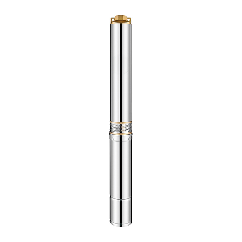
Multiple variables influence how much energy water loses as it travels upward. Evaluating these dimensions allows you to engineer a more efficient extraction system.
Pipe diameter and friction loss share an inverse relationship. Increasing the pipe diameter reduces the fluid velocity. A larger pipe reduces the fluid ratio per total area of the inside diameter. Less water touches the pipe walls relative to the total volume. This drastically cuts friction energy loss.
Engineers must balance friction reduction against sediment transport. Industry standards dictate strict velocity limits. You should maintain fluid velocity between 3 to 7 feet per second. Velocities below 3 feet per second allow suspended solids to settle. Sediment buildup eventually clogs the riser pipe. Velocities above 7 feet per second generate extreme friction. This wastes energy and accelerates pipe wear.
Calculate peak flow demand in gallons per minute (GPM).
Select a nominal pipe size.
Verify the resulting velocity falls within the 3 to 7 feet per second range.
Adjust pipe diameter up or down to optimize the velocity.
Friction loss accumulates over distance. It remains directly proportional to the total length of the pipe. Deeper wells inherently generate higher friction head simply due to the extended travel distance. A 500-foot well generates twice the pipe friction of a 250-foot well, assuming identical flow rates and pipe diameters. You must account for every foot of pipe, including surface manifolds, pitless adapters, and elbows.
Internal surface roughness alters the friction coefficient. Smoother walls create less drag. Engineers use the Hazen-Williams C-factor to quantify this roughness. A higher C-factor indicates a smoother pipe. Smoother pipes reduce the required head. This improves the efficiency of a deep well water pump.
Pipe Material | Hazen-Williams C-Factor | Friction Characteristics |
|---|---|---|
PVC (Polyvinyl Chloride) | 150 | Extremely smooth, minimal friction loss, resists scaling. |
Fiberglass | 150 | Smooth internal surface, highly corrosion resistant. |
New Carbon Steel | 140 | Moderate friction initially, degrades over time. |
Old/Corroded Steel | 90 - 100 | High friction, significant drag, requires higher pump head. |
The Hazen-Williams formula remains the industry standard for calculating friction loss in water systems. The formula requires the flow rate in gallons per minute, the internal diameter of the pipe in inches, and the C-factor of the pipe material. The resulting number gives you the friction loss in feet of head per 100 feet of pipe. You then multiply this number by the total pipe length divided by 100. This calculation provides the exact friction head you must add to your static lift.
Flow rate drives friction loss harder than any other variable. Friction loss increases with the square of the flow rate. Doubling the water volume quadruples the friction resistance. You must size the pipe to accommodate peak flow demands, not just average usage.
Fluid viscosity also plays a role. Standard groundwater maintains a relatively constant viscosity. Temperature variations in water wells remain minimal. However, industrial applications pumping heavier fluids must use Darcy-Weisbach calculations. Thicker fluids generate substantially more friction against the riser pipe walls.
Friction loss does not just waste energy. It physically alters how the equipment operates within the well casing. Understanding this interaction prevents catastrophic equipment failure.
Every well has a unique system curve. You plot this by combining static head with varying friction head at different flow rates. The system curve sweeps upward on a graph. Friction increases as flow increases.
Manufacturers provide a pump performance curve. This curve sweeps downward. The pump produces less head as flow increases. You must intersect your system curve with the pump curve. This intersection point dictates actual real-world performance. You want this intersection to land at the pump's Best Efficiency Point (BEP). Operating at the BEP minimizes radial thrust on the bearings and maximizes motor life.
Excessive head loss reduces the water's available energy. The fluid loses momentum before reaching its destination. This decreases the distance it can travel. End-users experience tangible issues on site.
Industrial discharge systems fail to meet required pressure metrics at the manifold.
Agricultural irrigation sprinklers lose their spray radius, leaving crops dry.
Domestic setups suffer from inadequate flow and poor fixture pressure.
Storage tanks take significantly longer to fill, extending pump run times and increasing wear.
Underestimating friction leads to operational failure. Actual friction head can exceed the calculated TDH. This pushes a submersible borehole pump to its shut-off head. The pump continues to spin. Water ceases to flow. The trapped water absorbs the motor's kinetic energy. It rapidly heats up. The motor loses its cooling mechanism and burns out completely.
Operating Condition | Flow Rate | Motor Temperature | Equipment Risk |
|---|---|---|---|
At Best Efficiency Point (BEP) | Optimal | Stable / Cooled by flow | Minimal wear, maximum lifespan |
Right of Curve (Low Head) | Excessive | Elevated | Upthrust damage, cavitation |
Deadheading (Excessive Friction) | Zero | Rapidly spiking | Catastrophic motor burnout, melted internals |
Operating a pump far to the left of its curve due to excessive friction causes severe mechanical stress. The pump generates high head but moves very little water. This creates massive downward thrust on the motor bearings. The thrust bearings absorb this load. Over time, the excessive weight causes the bearings to fail. The impellers then drop and grind against the bowls. This destroys the hydraulic integrity of the pump and requires a complete replacement.
Friction acts as a continuous financial drain. Every additional foot of friction head requires more horsepower to overcome. Operating a pump against high friction resistance consumes massive amounts of electricity.
Investing in a larger diameter riser pipe reduces discharge head. The initial material cost increases. However, the energy savings accumulate daily. A larger pipe often allows you to specify a smaller motor. This lowers both upfront equipment costs and long-term electrical consumption. Upgrading from a 4-inch to a 6-inch drop pipe on a high-yield agricultural well can drop the required motor size by a full horsepower tier.
High-volume extraction magnifies friction issues. Moving massive amounts of water requires strategic engineering to prevent system bottlenecking.
Engineers typically choose between two primary approaches when designing a system around a high capacity borehole pump.
System Design Strategy | Riser Pipe Sizing | Pump Selection | Hydraulic Efficiency | Mechanical Stress |
|---|---|---|---|---|
Approach A (Upsized Pipe) | Larger diameter | Lower horsepower, lower head | High | Low |
Approach B (Standard Pipe) | Smaller diameter | Higher horsepower, high head | Low | High |
Approach A involves upsizing the riser pipe. This minimizes friction. It allows for a smaller, lower-horsepower pump. This method prioritizes hydraulic efficiency. It requires a well casing large enough to accommodate the wider drop pipe.
Approach B utilizes a smaller riser pipe. Casing constraints often force this decision. You must specify a high-head, high-horsepower pump to overcome the severe friction. This method guarantees higher energy consumption. It also places more mechanical stress on the pump internals.
High friction generates immense backpressure. The pump internals must withstand severe thrust loads. Standard plastic or cast iron components often degrade under these conditions.
Specifying a stainless steel deep well pump solves this durability issue. Stainless steel impellers and bowls resist deformation. They maintain their hydraulic tolerances when operating at high pressures. They also resist the abrasive wear caused by high-velocity water flow. This ensures the pump maintains its performance curve over a longer lifespan.
Dynamic water levels complicate friction calculations. As the water table drops, static head increases. The pump moves left on its curve. Flow decreases. Friction decreases.
Variable Frequency Drives (VFDs) manage this dynamic environment. A VFD adjusts the motor's RPM. It optimizes flow rates to manage friction loss dynamically. The VFD slows the pump down during periods of low demand. This reduces velocity and cuts friction. It prevents the pump from running off-curve and protects the motor from overload conditions.
Install a pressure transducer at the surface discharge manifold.
Wire the transducer back to the VFD controller.
Program the target pressure setpoint into the drive.
Allow the VFD to automatically modulate motor RPM to maintain pressure while minimizing friction spikes.
Theoretical calculations often fail in the field. Real-world variables introduce hidden friction sources. Recognizing these risks prevents costly installation errors.
Many system designers focus solely on the vertical drop pipe. They ignore surface components. This guarantees an inaccurate TDH.
Failing to account for horizontal surface manifolds.
Ignoring the pressure drop across check valves, elbows, and pitless adapters.
Assuming downward-sloping surface pipes negate friction. They create negative static head, but friction loss still accumulates.
Using the static water level instead of the dynamic (pumping) water level. The water level drops when extraction begins. This increases the actual vertical lift required.
Pipes do not remain smooth forever. Mineral deposits build up on the interior walls. This scaling reduces the internal diameter of the pipe. Iron bacteria and corrosion create a rough, pitted surface.
Both conditions increase surface roughness and friction. The Hazen-Williams C-factor drops. The system curve gradually shifts steeper. This pushes the pump out of its Best Efficiency Point. Flow rates drop. Energy consumption spikes.
Degradation Type | Impact on Pipe | Impact on Friction Head |
|---|---|---|
Calcium Scaling | Reduces internal diameter | Increases velocity and friction exponentially |
Iron Bacteria | Creates slime and rough surface | Lowers C-factor, increases drag |
Oxidation/Corrosion | Pits the pipe walls | Creates turbulent flow, raising TDH |
Iron bacteria presents a unique challenge in deep well systems. These microorganisms feed on iron in the groundwater. They excrete a thick, slimy biofilm that coats the inside of the riser pipe. This biofilm drastically increases the surface roughness. A PVC pipe with a C-factor of 150 can drop to a C-factor of 100 within a few months if iron bacteria proliferates. You must account for this potential degradation when sizing the pump, or plan for regular chemical treatments to maintain hydraulic efficiency.
Anticipate degradation during the design phase. Recommend adding a safety margin to all friction loss calculations. A 5% to 10% margin accounts for future pipe scaling. It also covers unexpected surface routing changes during installation. This buffer ensures the selected borehole pump delivers adequate flow even as the system ages.
Conduct a thorough TDH audit of the proposed well design, measuring all vertical lifts, horizontal surface runs, and fitting restrictions.
Calculate the lifecycle energy costs comparing standard versus upsized riser pipe diameters to justify material upgrades.
Determine the dynamic pumping water level through a formal aquifer yield test before finalizing static head numbers.
Consult with a qualified pump engineer to specify the exact equipment configuration based on your friction-adjusted system curve.
Add a 10% safety margin to your final friction calculations to account for long-term pipe scaling and surface routing modifications.
A: Use the Hazen-Williams equation or Darcy-Weisbach formula. You must factor in the total pipe length, internal diameter, flow rate, fluid viscosity, and the specific material's roughness coefficient.
A: Gravity dictates the static head, which is the vertical lift. Friction head remains strictly a product of fluid moving against pipe walls. Downward slopes create negative static head, but friction loss still occurs and must be calculated into the TDH.
A: The orientation does not change the friction calculation itself. Friction loss occurs equally in horizontal and vertical pipes of the same length. However, vertical pipes must also overcome static head, whereas horizontal pipes only contribute to friction head.
A: High flow rates exponentially increase fluid velocity. Without a larger pipe diameter to accommodate the volume and reduce the fluid ratio per total area, friction loss spikes. This requires massive amounts of energy to overcome the resistance.
A: Yes. If underestimated, excess friction head pushes the pump to its shut-off head. This stops water flow entirely. The motor then overheats and fails rapidly due to a lack of cooling fluid moving past it.
A: Yes. Rougher materials like galvanized steel create more friction than smooth materials like PVC. This increases the Total Dynamic Head. You will potentially require a pump with a higher head rating to overcome the rougher pipe walls.


