
Views: 0 Author: Site Editor Publish Time: 2026-09-26 Origin: Site


The leading cause of premature groundwater system failure is a fundamental mismatch between aquifer recharge rates and pump extraction capabilities. We see this constantly in the field. Installing a pump that exceeds the borehole’s safe yield leads to rapid drawdown, dry running, cavitation, and motor burnout. Conversely, undersizing the pump results in a failure to meet peak hourly demand, rendering the water system inadequate for its intended application. Selecting the correct equipment requires moving beyond basic horsepower metrics. You need to look at the actual geology. This guide breaks down how to interpret hydrogeological yield data, calculate total dynamic head, and select a properly sized borehole pump that balances peak demand with long-term aquifer sustainability. We will walk through the exact steps to match your hardware to the ground conditions.
Yield Dictates Capacity: A pump’s flow rate must never exceed the tested "safe yield" of the borehole, typically calculated at 60% to 80% of the maximum constant test rate.
Data-Driven Selection: Proper sizing requires professional step-drawdown and constant-rate pump testing to determine static water levels, dynamic water levels, and recovery times.
System Protection is Mandatory: Even perfectly matched systems require electronic dry-run protection, flow restrictors, or Variable Frequency Drives (VFDs) to account for seasonal aquifer fluctuations.
Material Matters: Matching flow is only half the equation; selecting a stainless steel deep well pump ensures longevity in highly oxygenated or mineral-heavy drawdown zones.
Understanding the interaction between groundwater hydrogeology and mechanical extraction forms the foundation of system design. When a borehole sits idle, water rests at a specific depth. We call this the Static Water Level (SWL). You measure it by dropping an electronic dip meter down the casing until the probe hits water and beeps. Once extraction begins, the water level inside the casing drops. The pump removes water faster than the immediate surrounding aquifer matrix can replace it. Eventually, the water level stabilizes at a lower depth. This equilibrium point is the Dynamic Water Level (DWL).
The "Safe Yield" of a borehole represents the maximum continuous extraction rate that maintains the DWL safely above the pump intake. This ensures the system never runs dry. Exceeding this safe yield triggers a cascade of mechanical and geological failures. Mechanically, over-pumping forces the dynamic water level down to the pump intake. As the water level breaches the suction screen, the pump begins drawing in air alongside water. This creates a vortex.
Air entrainment leads to cavitation. Cavitation is a destructive phenomenon where low-pressure air bubbles implode against the spinning impellers. If you stand near the wellhead, it sounds like gravel passing through the pipes. These implosions pit the metal and shatter internal components. The motor also loses its primary cooling medium. Submersible motors rely on submerged flowing water to dissipate heat. Without it, you get rapid thermal overload and catastrophic stator burnout.
The geological consequences of over-pumping are equally severe. Forcing an aquifer to yield water faster than its natural transmissivity increases the velocity of water moving through the geological formation. High-velocity flow dislodges fine silt, sand, and abrasive particulates. The water drags them through the gravel pack and into the well screen. Over time, this sediment ingestion destroys the pump's hydraulics. It can even cause the borehole screen to collapse entirely. In localized, low-recharge aquifers, aggressive over-pumping permanently dewaters the fracture zones. You end up with a dry hole.
Under-pumping presents its own operational challenges. A pump sized significantly below the facility's peak hourly demand fails to maintain adequate surface pressure during periods of high usage. If a small pump runs continuously to fill a pressurized surface reservoir without generating sufficient flow, the system experiences short-cycling. The pressure switch rapidly toggles the motor on and off. This degrades the starting capacitor, stresses the electrical contacts, and drastically reduces the mechanical lifespan of the equipment.
Accurate sizing is impossible without empirical data. A formal hydrogeological yield test is the only reliable method to determine how an aquifer responds to pumping stress. The standard testing protocol begins with a step-drawdown test. During this phase, technicians pump the borehole at incrementally increasing flow rates. They typically use four to six distinct steps lasting one hour each. They monitor the dynamic water level at each step to identify the maximum potential yield and establish a baseline for the next phase.
Following the step-drawdown test, crews execute a constant rate test. They pump the borehole continuously at a specific, predetermined rate for 24 to 72 hours. This extended duration is necessary to observe long-term drawdown behavior. It helps identify boundary conditions. For instance, a borehole might yield excellent flow for the first twelve hours. Then, the dynamic water level plummets rapidly when the localized fracture network depletes. Constant rate testing reveals these hidden geological limitations before you install permanent equipment.
Executing these tests requires strict adherence to industry best practices. Here are the primary rules for yield testing:
Calibrate flow meters before starting the test to measure discharge rates accurately.
Use electronic dip meters to record real-time dynamic water level fluctuations down to the millimeter.
Never conduct yield tests immediately after the drilling rig leaves the site. Develop the borehole first using airlifting or surging techniques to clear residual drilling fluids and mud cakes.
Account for seasonal aquifer fluctuations. A yield test conducted during a wet season presents an overly optimistic safe yield compared to dry season realities.
Monitoring the recovery rate is just as critical as measuring the drawdown. Once the constant rate test concludes and the pump shuts off, technicians measure the time required for the water level to rebound to its original static position. If a borehole takes 14 hours to recover fully after a 10-hour pumping cycle, you must strictly limit the daily duty cycle of the permanent deep well water pump. This prevents long-term depletion of the aquifer recharge zone.
Beyond mechanical sizing, formal test pumping data is often a strict legal requirement. Environmental agencies and local water authorities require verified constant-rate test reports to support abstraction license applications. These regulations ensure that individual groundwater extraction remains within sustainable environmental limits. They prevent your well from negatively impacting neighboring wells or surface water ecosystems.
A common and dangerous pitfall in groundwater development is relying on driller estimates. Drillers often estimate yield by measuring the volume of water blown out of the hole by compressed air during the drilling process. This air-lift yield is a momentary snapshot of fracture capacity. It is not a sustained hydrogeological metric. Sizing a permanent pump based on an air-lift estimate almost guarantees premature system failure.
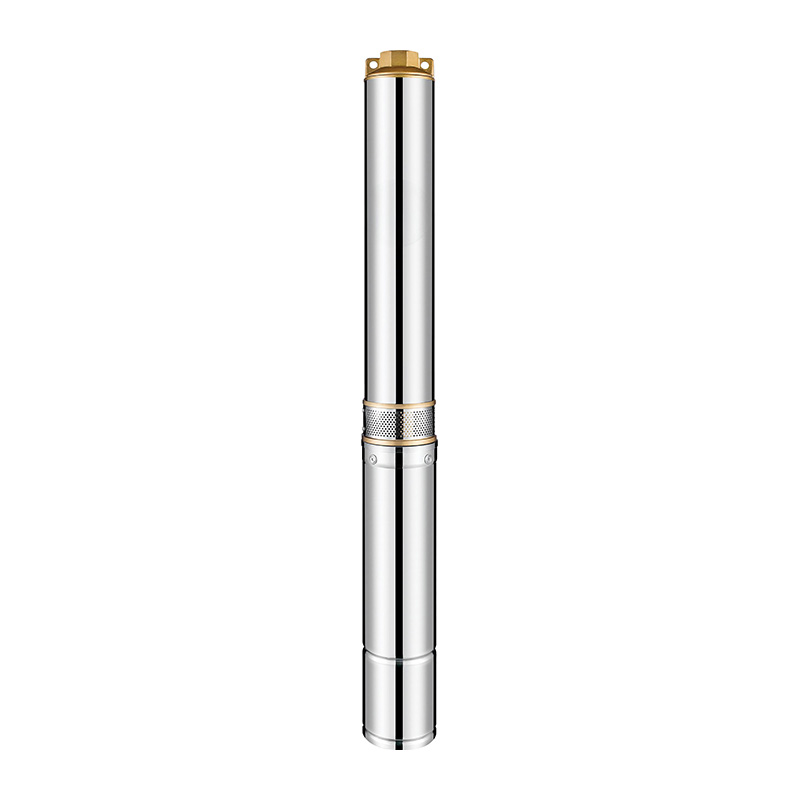
Once you establish the safe yield, the next engineering step is reconciling that yield with the actual water demand of the site. Establishing peak hourly demand involves calculating the absolute maximum volume of water required during the busiest hour of the day. For agricultural irrigation, this means running multiple sprinkler zones simultaneously. For residential or commercial facilities, it involves calculating concurrent fixture usage.
Conflicts frequently arise when the peak hourly demand exceeds the borehole's safe yield. In these scenarios, you cannot install a pump sized for the peak demand. It will rapidly pump the well dry. Instead, you must decouple the system architecture. You use a lower-flow pump, matched precisely to the safe yield, to extract water slowly over a 24-hour period. This pump discharges into a large surface storage tank. A separate, high-flow surface booster pump then draws from the storage tank to satisfy the peak hourly demand. This protects the aquifer while meeting user requirements.
Selecting the specific pump model requires rigorous analysis of manufacturer performance curves. A pump curve graphs the relationship between flow rate on the horizontal axis and head pressure on the vertical axis. Every centrifugal pump operates most efficiently at a specific point on this curve. We call this the Best Efficiency Point (BEP). The goal is to select a pump where the borehole's safe yield and the system's required pressure intersect as close to the BEP as possible. Operating too far to the left or right of the BEP causes excessive radial thrust on the pump shaft. This leads to premature bearing wear and mechanical seal failure.
Accurate pump selection also demands a precise calculation of Total Dynamic Head (TDH). TDH represents the total equivalent height that water must be lifted. It factors in gravity and friction. It is not simply the depth of the well. The calculation includes several distinct variables.
TDH Component | Description | Impact on Pump Sizing |
|---|---|---|
Dynamic Water Level (DWL) Depth | The vertical distance from the surface to the stabilized water level during continuous pumping. | Dictates the primary vertical lift requirement. Deep DWLs require multi-stage pump ends to generate sufficient upward force. |
Surface Elevation Lift | The vertical distance from the wellhead to the highest point of discharge, such as an elevated storage tank. | Adds direct static head to the system. You must measure this accurately with topographical data or laser levels. |
Friction Loss | The resistance generated by water flowing through drop pipes, elbows, valves, and surface piping. | Increases exponentially with higher flow rates. You can mitigate this by increasing the diameter of the drop pipe. |
Required Surface Pressure | The residual pressure required at the final destination, like 40 PSI for a residential pressure tank. | Converted to head (1 PSI equals 2.31 feet of head) and added to the total calculation. |
Optimizing the drop pipe diameter is a highly effective way to reduce TDH. Forcing a high volume of water through a narrow pipe generates massive friction loss. This forces the pump to work harder and consume more electricity. Upsizing the drop pipe by a single diameter increment significantly reduces friction. This lowers the overall TDH and potentially allows for the selection of a smaller, more energy-efficient motor.
We must debunk the persistent myth that a larger pump is inherently better. Installing an oversized high capacity borehole pump in an average-yield well creates severe operational instability. The massive pump evacuates the casing rapidly, hits the low-level shutoff, and stops. Minutes later, the well recovers, and the pump slams back on. This rapid cycling generates immense torque spikes. It overheats the motor windings and destroys the starting components. The extraction rate must always respect the geological speed limit of the aquifer.
The physical depth of the dynamic water level dictates the fundamental architecture of the pumping system. Surface pumps, including jet pumps and centrifugal suction pumps, rely on atmospheric pressure to push water up the intake pipe. Because atmospheric pressure is finite, physics dictates that a surface pump cannot lift water from a depth greater than 7 to 8 meters. This applies regardless of the motor's horsepower. When the dynamic water level drops below this threshold, a submersible borehole pump becomes a mandatory engineering requirement. Submersibles bypass the atmospheric limit entirely. They sit submerged in the water column and push the water to the surface under direct mechanical pressure.
The chemical composition of the groundwater heavily influences material selection. As a borehole is pumped and the dynamic water level drops, the previously submerged aquifer matrix is exposed to oxygen. This oxygenation process alters the localized water chemistry. If the groundwater contains high concentrations of dissolved iron or manganese, the introduced oxygen causes these minerals to precipitate out of solution. This creates highly corrosive and abrasive particulate matter. Boreholes located in coastal regions or deep sedimentary basins often exhibit high salinity or low pH levels.
In these aggressive chemical environments, standard cast iron or brass pump components degrade rapidly through galvanic corrosion and pitting. Specifying a stainless steel deep well pump is critical for long-term reliability. High-grade stainless steel forms a passive oxide layer that resists chloride attacks and acidic degradation. This ensures the hydraulic impellers maintain their precise tolerances over years of continuous operation.
Motor cooling is another vital architectural consideration. Submersible motors are designed to be cooled by the continuous flow of groundwater passing over the external motor housing before entering the pump intake screen. If a pump is installed above the well screen, water flows upward from the bottom of the well, passing over the motor perfectly. If hydrogeological conditions require the pump to be installed below the main water-bearing casing screen, the water enters from above and gets sucked directly into the intake. This leaves the motor sitting in stagnant, uncooled water. In these top-feeding installations, you must fit a flow sleeve over the pump. This physical barrier forces the incoming water to travel down past the bottom of the motor and back up into the intake, guaranteeing adequate thermal dissipation.
Determining the exact installation depth of the pump requires careful analysis of the borehole log and the yield test data. Consider a common real-world scenario. A drilling crew sinks a borehole to a total depth of 65 meters. The static water level rests at 20 meters. It might seem logical to sink the pump as deep as possible, perhaps to 60 meters, to maximize the available drawdown column. This is a dangerous miscalculation. The bottom few meters of any borehole act as a sump zone. This area collects fine sediment, drilling debris, and precipitated minerals over time.
Placing the pump intake directly in or just above this sump zone guarantees severe sediment ingestion. Sand and grit will rapidly destroy the impellers and mechanical seals. The strict rule of thumb is to install the pump safely below the lowest anticipated dynamic water level. You must include seasonal drought adjustments in this calculation. Ideally, place it above the primary water-bearing fracture zones to ensure proper motor cooling. Absolutely never place it less than 2 to 3 meters above the absolute bottom of the borehole.
Modern groundwater systems increasingly rely on Variable Frequency Drives to manage the delicate balance between pump flow and borehole yield. A VFD replaces the traditional on/off pressure switch. It monitors the surface pressure in real-time and adjusts the electrical frequency supplied to the motor. It speeds the motor up or slows it down to match the exact water demand. If a borehole has a marginal yield, you can program a VFD to cap the maximum motor speed. This effectively throttles the pump's output to ensure it never exceeds the aquifer's safe yield, all while maintaining a constant, smooth pressure at the surface.
Even with perfect sizing and VFD integration, environmental unpredictability demands robust fail-safes. Aquifer levels drop unexpectedly due to regional droughts or heavy extraction by neighboring agricultural operations. Dry-run protection is non-negotiable. You achieve this through physical water level probes suspended in the borehole just above the pump intake. If the water level drops below the conductivity electrode, the control panel instantly severs power to the motor. Alternatively, modern under-load monitoring relays analyze the electrical current drawn by the motor. If the pump begins to draw air, the mechanical load drops instantly. The relay detects this sudden drop in amperage and shuts the system down before thermal damage occurs.
Commission a formal step-drawdown and constant-rate yield test to establish your baseline safe yield.
Calculate your facility's peak hourly demand and design surface storage solutions if that demand exceeds the safe yield.
Calculate the Total Dynamic Head accurately by factoring in friction loss and surface elevation changes.
Review performance curves with a pump engineer to verify the Best Efficiency Point before procurement.
Install electronic dry-run protection and integrate a Variable Frequency Drive to optimize long-term extraction rates.
A: An oversized pump extracts water faster than the aquifer can recharge, causing rapid drawdown. The water level drops to the intake, leading to air entrainment, cavitation, and dry running. This causes severe mechanical damage, frequent breakdowns, motor burnout, and can trigger the geological collapse of the borehole screen due to excessive water velocity drawing in sediment.
A: Install the pump below the lowest anticipated dynamic water level to prevent dry running, but well above the bottom of the well. In a 65m borehole, do not drop the pump to 60m, as it will sit in the sediment sump zone. Keep it at least 2 to 3 meters above the bottom, ideally above the main water-bearing fractures.
A: We highly discourage this practice. Doing so requires advanced electronic intervention, such as a Variable Frequency Drive, to artificially throttle the motor speed and restrict the flow rate. Without strict level-control automation and VFD throttling, a high-capacity pump will immediately evacuate the casing, run dry, and suffer catastrophic mechanical failure.
A: Conduct a formal yield test immediately after initial drilling and well development. Repeat the test if you notice a significant, unexplained drop in water output, when applying for or renewing environmental abstraction licenses, or before replacing a failed pump to ensure aquifer conditions have not changed over time.
A: Short-cycling occurs when a pump rapidly turns on and off. This happens if the pump is oversized for the surface pressure tank, if the pressure tank's internal bladder has ruptured and lost its air charge, or if the pump fights massive friction loss and hits its pressure cut-off limit instantly without moving sufficient water volume.


